Interdata Systems (Perkin-Elmer)
Interdata Model One
I was given two of these systems in 1979. They had been in storage for several years before I obtained them and I have had them in storage for the last 34 years. One is missing the core memory board but the other is complete enough to operate. I powered them up with a variable transformer slowly to check for any shorted capacitors or power supply issues but they came up just fine with all voltages looking good. Not bad for a nearly 50 year old system! They both have problems with possible stuck bits, however I can examine memory and it looks like it’s trying to execute instructions when stepping through memory. I don’t have a schematic but I do have a programmers user guide which has all the instruction set and a good block diagram of the CPU. It’s similar to other Interdata models (3 & 4) so hopefully I will be able to find more documentation to help me restore it to working order.
The Model 1 is mostly 7400 series TTL with some DTL chips mixed in. There is no LSI chips and all registers and ALU done with basic gates. The CPU consists of 4 ten inch boards (control 1, control 2, control 3, register).
There is no UART for the teletype interface. The serial to parallel conversion and timing is all done through software. It does have a current loop interface for the teletype that converts the serial line to TTL levels and sends / receives bits through the carry bit with a special instruction. There are several programming examples in user’s guide.
I hope to restore the system enough to load simple programs to demonstrate the system in operation.
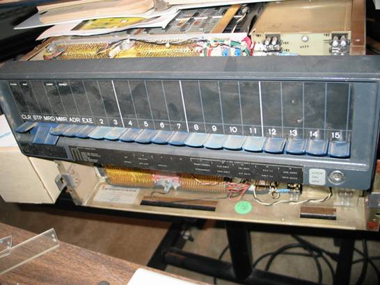
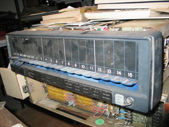
Model One front panel (the one below had the front panel removed showing the backplane).
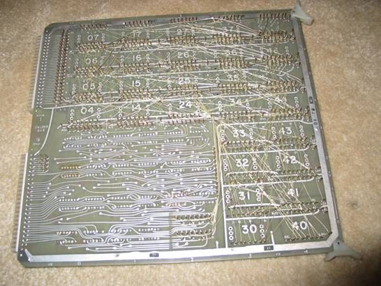
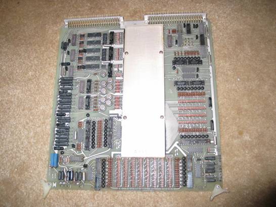
Model One Core Memory board (2K).
Model One 10-inch chassis from the back, with Control 1, Control 2, Control 3, Register, Core boards.
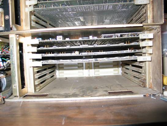
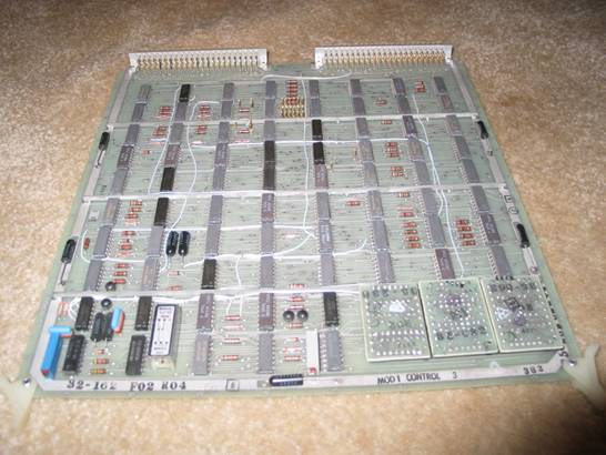
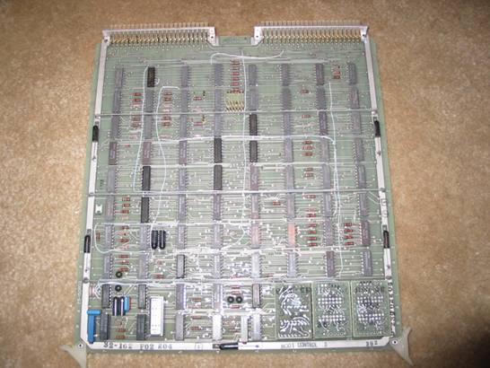
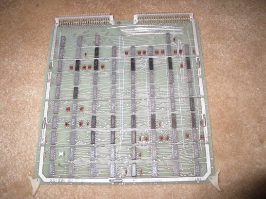
Control 3
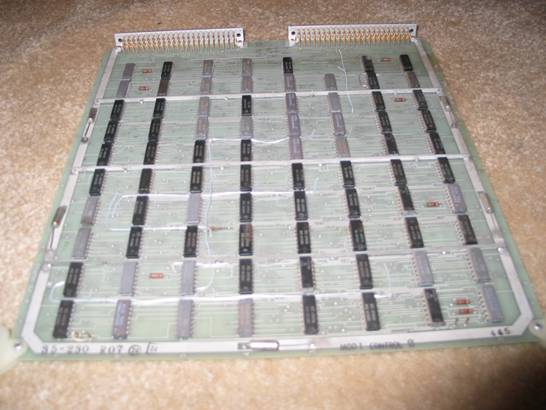
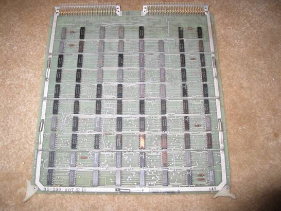
Control 2
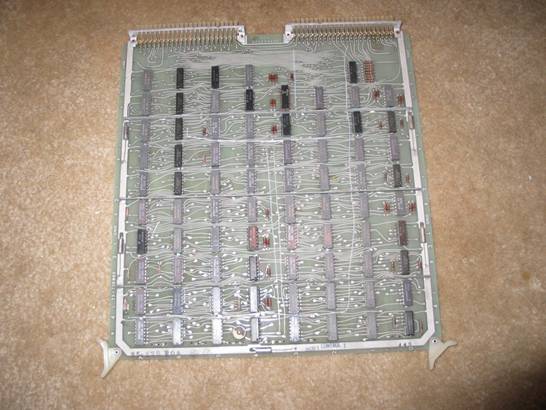
Control 1
Control 3
Core Memory board (2K)
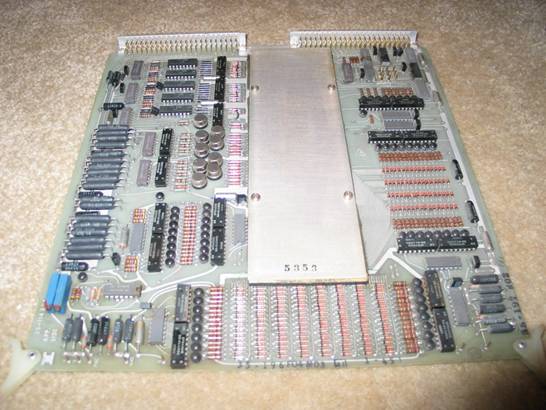
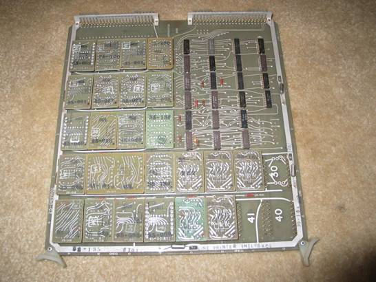
I/O card – Line Printer Interface (may be from a model 3 or 4)
Back side of the Interface board. Note the wire-wrap section used to customize the interface.